3.1
Draw a block diagram of PCM clearly explaining how a basic frame
structure is achieved in each block.

| Bits/Time slot |
= |
8 |
| Total number of bits in the
PCM frame |
= |
8 * 32 |
| Data rate of the frame |
= |
256/125µs |
| |
= |
2.048Mbit/s |
| Time taken for one slot |
= |
125/32 |
| |
= |
3.9µs |
| Data rate of a slot |
= |
8/3.9 µs |
| |
= |
64kBit/s |
This gives a PCM frame of 32 time slots (each
with 64Kbit/s rate) at a data rate of
2.048Mbit/s where time slot 0 is used for synchronizing while time
slot 16 is used for
synchronizing.
3.2
A PCM system will comprise of sampling, quantizing and encoding.
Explain each block. clearly.
Sampling:
Sampling a band limited analog signal at a frequency higher than
twice the
maximum frequency of the analog signal
Quantizing:
Non-linear quantizing of sampled values
Sampling Quantizing Encoding
Encoding:
Assigning ‘0’s and ‘1’s for the quantized
voltage levels
Sign: + or – (1-bit)
Segment No.: 3-bits
Level No.: 4-bits
3.3
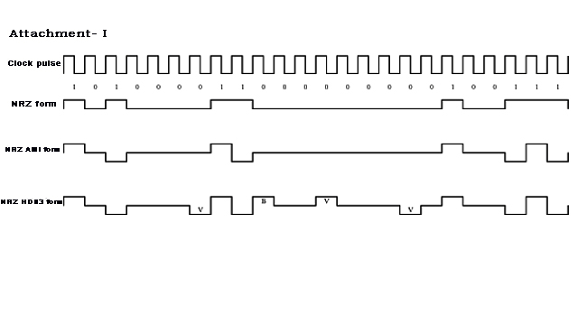
Three consecutive voice samples in a 30 channel PCM system are identified
as follows.
+50V, 0V, -68V
Draw the wave forms that you can observe in the transmission media,
assuming HDB3 transcoding.
(Assuming A-Law compression for non-linear quantizing)
|